
One afternoon, Dimi and I decided to mess with some red, green, and blue LEDs. The three lights were on a chip which was located in the corner of one of those forest green circuit boards you see when you take apart an old DVD player or computer. So the lights were stuck there on the board; they received a voltage and a current that we could not easily change and therefore we had no control over how brightly each LED shone. But we could turn each LED on and off really quickly, like a strobe light in a haunted house, or blinking multicolored Christmas lights, but faster. I wanted to make my favorite color, purple. But how to make purple light with red, green, and blue? First, a bit of Color 101.
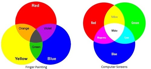
The lights in our TV’s, projectors, computer screens, and LED’s don’t follow the same color system as the one you learned in grade school art class.When kids play with finger painting, they learn that there are three primary colors: red, blue, and yellow. Any combination of those three can produce whatever color you can imagine. If the messy kid next to you decides to go HAM and mix all of the colors, suddenly they are left with brown or black.
But, if you’re working with light, it’s the complete opposite: mix all of the colors together and – as anyone who’s ever played with a kaleidoscope or prism or seen Pink Floyd’s Dark Side of the Moon album cover, you know this one – you get white.
With light, the primary colors we use are red, green, and blue – this is why whenever you turn on a projector that funky screen appears with RGB at the bottom. (Random sidenote: RGB is also my initials and I truly believed the CIA was trying to send me messages through the projector – but you know it’s cool it’s this color thing too). Fancy color people call the finger painting system ‘subtractive’ and the light system ‘additive’ when they describe the two color systems, as seen side-by-side in the images below.
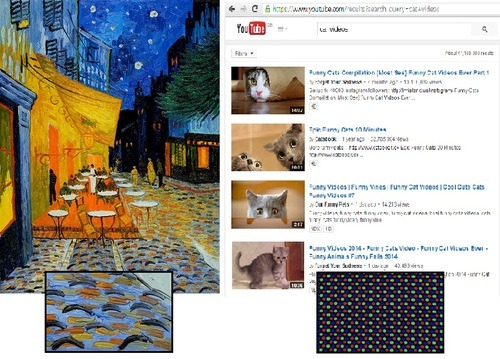
Like an impressionist painting, millions of these tiny red, green, and blue dots combine on your computer screen to allow you to read these words or watch your favorite movie. (You may even be able to take a magnifying glass to your screen and see it yourself).
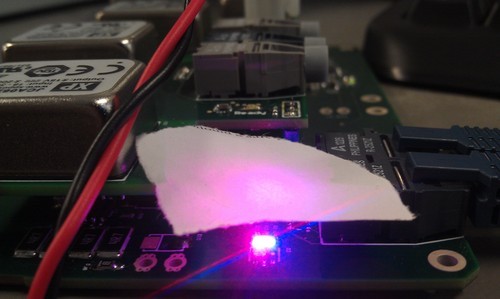
Back to Dimi’s and my experiment with purple light. We knew combining red and blue make purple. And, since we couldn’t control the brightness or where the LED’s shone their light, we decided to control how long each light was turned on. By quickly switching between the red light being on and the blue light being on, the average could become purple. We did this by sending a square signal to tell the switch when to turn on and off, as seen in the picture below.
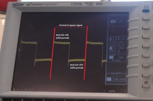
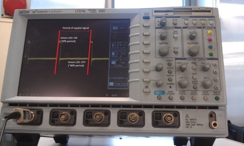
This is the square signal turning the red LED on and off. The time in between the two red lines represent the period of the square signal – the pattern within the two red lines will repeat over and over again until we tell it to do something else. So if we want red and blue to be on an equal amount of time, we tell the red light to stay on for half of the period time and then turn off for the other half of the period time. The period time can be really small – on the order of microseconds – which means your eye sees the two lights rapidly flickering. When we implemented this and looked at the LED’s directly, they were too bright and you could still see two individual lights – and that wouldn’t work. So we put a piece of paper over the two separate lights to act like a filter/surface for the lights to converge onto, and behold! Purple!
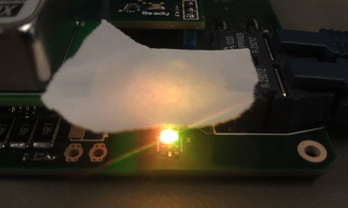
But what about orange? In our new RGB system, orange is a combination of red and green. But this time, we needed to combine different levels of red and green light. When we made purple before, we could turn the red light on for half of the time and then turn the blue light on for the other half of the time. But for orange, we needed approximately 80% of the light to be red and 20% to be green – so we told the switches to spend more time keeping the red light on and less time keeping the green light on. (This makes our square signal look more like a rectangle, but for some reason we still call it a square signal.) The signal shown below shows the green LED: the period in between the two red lines shows the green LED is on for a small percentage of the period and off for the rest of it. The signal for the red LED would be exactly the opposite.
The piece of paper helps to combine the two lights and shows orange on its surface (the picture turned out more yellow, but you get the point.)
Changing that square signal allows us to change what color light we see, right? Congratulations, you now understand Pulse Width Modulation (PWM). In electronics, instead of controlling what shade of color we see on a piece of paper, we use PWM to control other things like voltage. Instead of a piece of paper, we use inductors and capacitors to average things out. Our lightswitch turning each LED on and off is called a transistor. PWM is simply a square signal that turns the transistor on and off – like your finger turning on and off a light switch. Instead of your brain controlling your finger, we use programming to control what the square signal looks like. The square wave is a voltage wave, and thus we can look at the image on an oscilloscope (the fancy machine with all the knobs that showed us the square signals earlier).
In truth, color has nothing to do with my research this summer. Dimi and I were just messing around with some indicator lights one afternoon. But Pulse Width Modulation does. My work this summer surrounded building a converter: a device that converts the three-phase alternating current a motor produces to the direct current our laptops and cell phones consume. We use PWM to help accomplish this. See future posts for more on converters!